


Hi, my name is Bob Greenyer and welcome to RemoteView.ICU
The following is my curated attempt at machine assisted translation of the awarded patent of Anatoly Kladov, using several sources, including those available on Russian and European patent servers and the original part typed and part hand written patent document. In all cases there were problems with the official sources, however, by combining them and re-constructing and verifying the key equations, I believe this is a workable document that gets across the bulk of the original intent of the patent.
If you want to refer to the original documents to check, they are available from my blog article “ULTR - Method for Obtaining Energy” alongside a discussion of this document. Also, you will find my proposed possible reactions that could account for:
the extra COP produced during addition of 5% aluminosilicate suspension,
the production of Beta/Gamma radiation following the addition of ‘an amount of CO2’ and
the production of neutrons, following the addition of LiCl.
These are my current best proposals to explain the phenomena observed based on my experience, I welcome any other suggestions. So, onto the patent.
RU2054604C1
FIELD: power engineering.
EFFECT: increased efficiency.
9 figures, 1 table
Abstract
The proposed method of obtaining energy involves feeding a liquid phase substance into a treatment zone where cavitation bubbles are created in the substance by producing a fluctuating pressure, with constant and variable components, based on the following relationships:
P1 = from 0.3 to 0.7 (P2+P3); and
P2 + P3 - P1 = from 1 to 10σ,
in which:
P1 - represents the constant pressure component (in MPa),
P2 - represents the variable pressure component (in MPa),
P3 - represents the saturated vapour pressure (in MPa) of the substance being treated at the temperature at which it is fed into the treatment zone, and
σ - is the tensile strength of the substance being treated at the temperature at which it is fed into the treatment zone (in MPa).
Description
The invention relates to energy, in particular to the energy of strong interactions of elementary particles.
Currently, there are many methods for producing energy that are widely known, for example, the method of generating thermal energy from solar radiation, kinetic energy from wind, water, thermal energy released during the burning of fossil fuels (coal, oil, gas), thermal energy released during the fission of heavy nuclei of chemical elements, the energy released during the fusion of the light nuclei of chemical elements, the energy released during the fusion of matter and antimatter.
However, the radiation intensity of solar energy in the optical range is only a few 100 watts per square meter of surface. Therefore, a huge area is required to obtain the energy of solar radiation on an industrial scale.
Wind energy is also characterised by low intensity despite the fact that it is two to three orders of magnitude higher than the intensity of solar radiation.
The energy concentration of moving water is two to three orders of magnitude greater than that of wind energy. This value of about one MW per square metre is acceptable for commercial production of energy from moving masses of water, which is confirmed by the development of hydropower. Negative factors in this case are the need to create reservoirs and the flooding of large areas of the Earth's surface, high capital costs for the construction of hydropower facilities and limited resources.
The energy released during the burning of fossil fuels (coal, oil, gas) is currently the main type of energy used on an industrial scale. Negative factors are environmental pollution during the extraction and transportation of fuel, fuel combustion products and heat, while the efficiency of thermal stations does not exceed 40% for mines, open pits, ash dumps, heaps, heat plants, cooling ponds, power lines and other structures included in the fuel-energy complex. Huge areas are allocated, which is a consequence of insufficient concentration of energy.
A widely known method of generating energy is at thermal power plants. This method consists in burning organic fuel in the furnace of a steam boiler, where the chemical energy of the fuel is converted into the thermal energy of water vapour.
However, for the implementation of this method requires a large energy consumption for the extraction of fossil fuels, for its transportation and combustion. In addition, fuel combustion leads to environmental pollution. At the same time, a large amount of substance at the stage of combustion is released into the atmosphere and hydrosphere in the form of gaseous products of combustion. Of all the chemical energy contained in fossil fuels, only about 30% reaches the consumer in the form of electrical energy. The rest is scattered in the environment, which reduces the efficiency of thermal power plants and upsets the ecological balance of the environment.
A widely known method of generating energy at nuclear power plants is that water is supplied to the active zone of a nuclear reactor, where it is heated using nuclear fuel. Heated water is removed from the treatment area for subsequent use as intended.
However, the costs of extracting and preparing nuclear fuel for a nuclear reactor are high, which negatively affects the cost of energy received. In addition, nuclear fuel cannot be fully used in a nuclear reactor, which significantly reduces the efficiency of the latter. Moreover, the fuel of nuclear power plants is used about thirty times less efficiently than that used in thermal power plants.
Potentially, the development of nuclear energy poses serious problems related to environmental protection. Accidents that occurred at a number of nuclear power plants convincingly testify to this.
A known method of obtaining energy, which, according to its essential features, is the closest to the invention, is US Patent No. US4333796A (19 May 1978). This method involves supplying liquid lithium to the treatment zone, where it is subjected to periodic acoustic forces to create cavitation bubbles in it, resulting in a fusion reaction.
The basis of the invention is the task of creating a method of producing energy that would eliminate the costs of production, preparation and transportation of fuel, and would also allow to use any substance in a liquid state as a working medium.
This problem is solved by creating a method of generating energy, including feeding the substance in the liquid phase to the treatment zone and creating cavitation bubbles in the substance. While according to the invention, cavitation bubbles in the substance are made by creating a periodically changing pressure having constant and variable components, and these components are selected from the following ratios:
P1 = from 0.3 to 0.7 (P2+P3); and
P2 + P3 - P1 = from 1 to 10 σ,
in which:
P1 - represents the constant pressure component (in MPa),
P2 - represents the variable pressure component (in MPa),
P3 - represents the saturated vapour pressure (in MPa) of the substance being treated at the temperature at which it is fed into the treatment zone, and
σ - is the tensile strength of the substance being treated at the temperature at which it is fed into the treatment zone (in MPa).
Subject to the indicated conditions of simultaneous action of alternating and static pressures on a substance in a liquid phase, cavitation bubbles form in a liquid at the moment when the sum of two quantities: the amplitudes of the alternating pressure and the pressure of saturated vapour of a substance at a given temperature, exceeds the sum of two values: static pressure and fluid tearing strength at a given temperature. This moment in time coincides with the moment of action of the negative half-wave of variable pressure.
During the action of a positive half-wave of alternating pressure on the liquid, the sum of two pressures acts on the cavitation bubbles: the amplitude of the alternating pressure and the static pressure, which tends to compress the bubbles, that is to say, it slams them. At the moment of collapse of the bubbles, their walls under the action of the pressure difference acting on the cavitation bubbles accelerate, acquire kinetic energy and collide in the centre. The magnitude of the kinetic energy acquired is sufficient to break the bond between the nucleons, overcome the repulsive forces of the nuclei and initiate interaction between the elementary particles contained in the nuclei of the processed substance (neutrons, protons). As a result, in the local area of matter, at the moment of the disappearance of the cavitation bubble (its collapse), nuclear reactions occur with the release of a large amount of energy. The energy released in the treatment area is converted into heat in a liquid. This heat is continuously removed from the treatment zone in the form of a heated liquid and used as necessary, and the cooled liquid is returned to the treatment zone.
If it is necessary to change the energy production, vary the alternating pressure and/or constant pressure within the specified limits. In this case, the specified ratio of alternating and constant pressures must be observed, because if it is violated, either by increasing the alternating pressure above the specified pressure or by decreasing the constant pressure below the specified pressure, cavitation bubbles of a large size are formed in the fluid which do not have time to slam, as a result, the energy release is terminated.
In the case of increasing the constant pressure above the specified pressure or decreasing the alternating pressure below the specified pressure, cavitation bubbles in the liquid cannot be formed and therefore no energy production will occur, since in this case, the tensile stresses in the treated liquid will be less than the tensile strength of the liquids.
Brief description of Illustrations
The proposed method of generating energy can be carried out in a known ultrasonic activator (application PCT / RU92 / 00195), which will be described below. For a better understanding of the invention, specific examples of its execution are given with reference to the attached drawings, wherein:
Fig. 1 schematically shows an ultrasonic activator in which the proposed method can be implemented;
Fig. 2 and 3 present diagrams of experimental setups for implementing the proposed method;
Fig. 4 and 5 show a graphical dependence of the amount of energy released from the magnitude of the variable and static pressures;
Fig. 6 and 7 graphical dependence of γ + β-radiation on the composition of the processed substance in the implementation of the proposed method;
Fig. 9 shows graphically the dependence of neutron radiation on the operating mode of the setup shown in Fig. 3, and on the distance between the neutron detector and the ultrasonic activator in the implementation of the proposed method.
The preferred embodiment of the invention
The processed liquid, for example water, is fed into the ultrasonic activator, schematically depicted in Fig. 1. The ultrasonic activator contains two or more working chambers 1, connected in series (there are four in this example), in each of which impellers 2 of a centrifugal pump are installed with rotors 3 fixed on the periphery in the form of perforated rings. Coaxial to the rotors 3 in the cases 4 of the working chambers 1, opposite each rotor 3, is a stator 5, made in the form of a perforated ring. The working chambers 1 are interconnected by means of diffusers 6. The last working chamber 1 is connected to the first chamber 1 by a circulation circuit 7.
Ultrasonic activator operates as follows
During rotation, the impeller 2 of the centrifugal pump gives kinetic energy to the fluid being processed, which is partially converted into static pressure (in diffusers 6), and partially into alternating pressure (when passing the perforations of rotor 3 and stator 5).
Depending on the selected fluid, its temperature and the calculated values of static and variable pressures that satisfy the above dependencies, the design and technological parameters of the ultrasonic activator are established and maintained (see PCT / RU 92 / 00195).
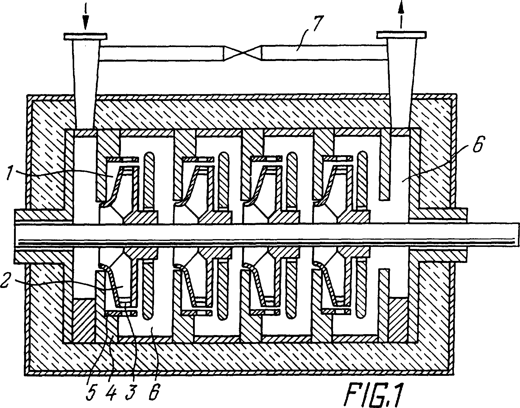
During the period of the negative half-wave of the alternating pressure, cavitation bubbles are formed in the liquid in the treatment zone. During the next positive half-wave of the alternating pressure the cavitation bubbles are collapsed in the liquid in the treatment zone. By the end of this half-period, the bubbles deposit kinetic energy determined by the difference in pressure acting on the bubbles from outside and inside. From the outside, the sum of alternating and constant pressures acts on the bubbles. Inside the bubbles, it is the pressure of saturated vapours of the liquid that acts on them. In addition, other forces, determined by the physical and chemical properties of the liquid and the absolute pressure of the vapour, also influence the motion of the bubbles.
At the moment the bubble disappears (at the moment of its collapse), the kinetic energy is converted into the collision energy of elementary particles. The energy released during the collapse of the bubble is several orders of magnitude higher than the binding energy of elementary particles (nucleons) in the nucleus. As a result of a collision of nuclei in the conditions of the proposed method, an interaction occurs between elementary particles of the constituent nuclei. The energy released in the reactions, controlled by the described method between elementary particles, is converted into thermal energy in a liquid, and it is removed from the treatment zone with a liquid stream.
In specific examples of the implementation of the claimed method, experiments are described that are performed in experimental installations with open and closed cycles (Figs. 2 and 3). The installation shown in Fig. 2, contains an ultrasonic activator 8, the description of which is given above, an electric motor 9 for activating the activator, a power meter 10 for measuring power consumption, a device 11 for measuring the temperature of the processed fluid at the input and output, a radiometer 12 for measuring γ and β-radiation with a radiation detector 13, a neutron radiometer 14 for measuring neutron flux with a neutron detector 15, a manometer 16 for measuring static pressure, a device 17 for measuring alternating pressure, a device 18 for measuring liquid flow rate and a device 19 for measuring the frequency spectrum of alternating pressure. A valve 20 is installed on the pipeline discharging liquid from the installation. Valve 21 is installed between pipelines discharging and supplying liquid to the installation.
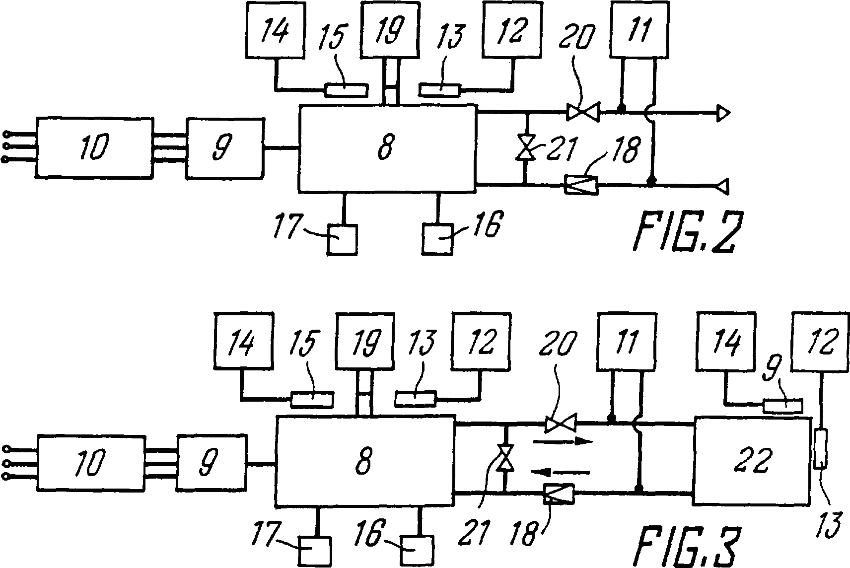
Installation works as follows
Liquid, such as tap water, is piped to the inlet of the installation. The valve 20 sets the amount of water flow passing through the ultrasonic activator 8, where they support the above calculated ratio of variable and static pressures. To change the static and variable pressures within the specified limits, valve 21 is used. Having established the necessary operating mode of the installation, they are allowed to stand for 10-15 minutes to achieve stable operation, at a given mode and make the necessary measurements. The power consumption (N1) is measured by a wattmeter 10. The generated thermal power (N2) is determined by the product of two measured quantities: the difference (Δt) of the temperature at the inlet and outlet of the activator 8, measured using the device 11 and the flow rate (G) of the fluid passing through the activator 8, measured by the device 18, and the heat capacity constant (c) of the treated fluid:
N2 = Δt•G•c (W) (1)
Instruments 16 and 17 for measuring pressure are used to monitor the operation mode of the installation. The frequency spectrum of the variable pressure is measured by a spectrometer 19.
Using radiometers 12 and 14 with their detectors 13 and 15, the fluxes of ionising radiation are measured.
After all of the above measurements, we can conclude that the power consumption for the implementation of the proposed method is on average two to three times less than the heat output released as a result of the proposed method. Moreover, ionising radiation released during the implementation of the proposed method does not exceed the natural background.
To confirm the existence of nuclear reactions in cavitation bubbles of the treated liquid and the formation of γ, β and neutron radiation when implementing the proposed method the installation shown in Fig. 3 is used. This installation is made similar to the above described and depicted in Fig. 2 however, it differs from the latter due to the presence of a container 22 for the accumulation of these radiations to a value that can be measured by available instruments. The fluid in this case circulates in a closed loop between the ultrasonic activator 8 and vessel 22 for as long as it takes to accumulate a level of radiation that is measurable.
To more clearly confirm the occurrence of nuclear reactions in cavitation bubbles of the liquid being treated, additives of stable isotopes (oxygen, nitrogen, carbon, sodium) were used, which, as a result of nuclear reactions occurring in activator 8, turn into unstable isotopes, which were recorded using radiometers 12 and 14.
Thus, when implementing the proposed method, it becomes possible on an industrial scale to obtain the energy of strong interaction of elementary particles.
Example 1
The strong interaction energy of elementary particles formed in tap water at a temperature of 20°C is obtained. This water at this temperature has a tensile strength of approximately 0.35 MPa. The pressure (P3) of saturated vapours at the indicated temperature is approximately equal to zero.
By dependencies:
P1 = 0.3 (P2 + P3); and
P2 + P3 - P1 = σ,
solve the system of these equations to find the constant pressure (P1) and variable pressure (P2) necessary for the proposed method:
P1 = 0.3 P2; and
P2 - 0.3 P2 = σ;
Tap water at a temperature of 20°C is fed into the ultrasonic activator shown in figure 1., where, by acting on the valves 20 and 21 shown in figure 2, using measuring instruments 16, 17 and 19, the variable and constant pressures defined above can be established.
When passing tap water through an ultrasonic activator, the water is heated as a result of strong interaction of elementary particles. Heated water is removed from the activator and sent through the pipeline to the consumer of thermal energy. After transferring thermal energy to the consumer, the chilled water is either discharged into the sewer or returned to the activator for reuse.
Using a wattmeter 10, the electrical power consumption (N1) to realise the proposed method was measured, which was equal to 6 kW. The power produced (N2) according to the above expression (1), in this case is equal to 6.5 kW.
Dividing the electric power consumption (N1), which in this case is 6 kW, by the produced power (N2), which is 6.5 kW, a coefficient (k) of 1.08 is obtained.
Examples 2-12
These were performed in a similar way to that described in Example 1. The substance under processing, its temperature, treatment parameters (P1, P2, P3, σ), power consumption (N1), heat output (N2) and coefficient (k) are given in Table 1.
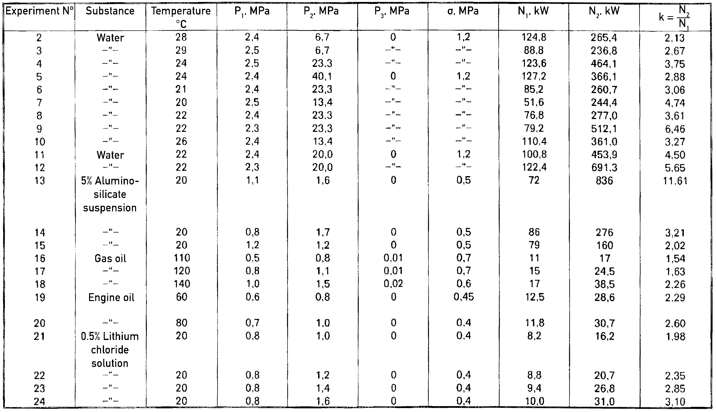
The table shows that when processing various substances in the liquid phase at certain variable and static pressures lying within the specified limits (i.e., when implementing the proposed method), the energy received is several times greater than the energy consumed.
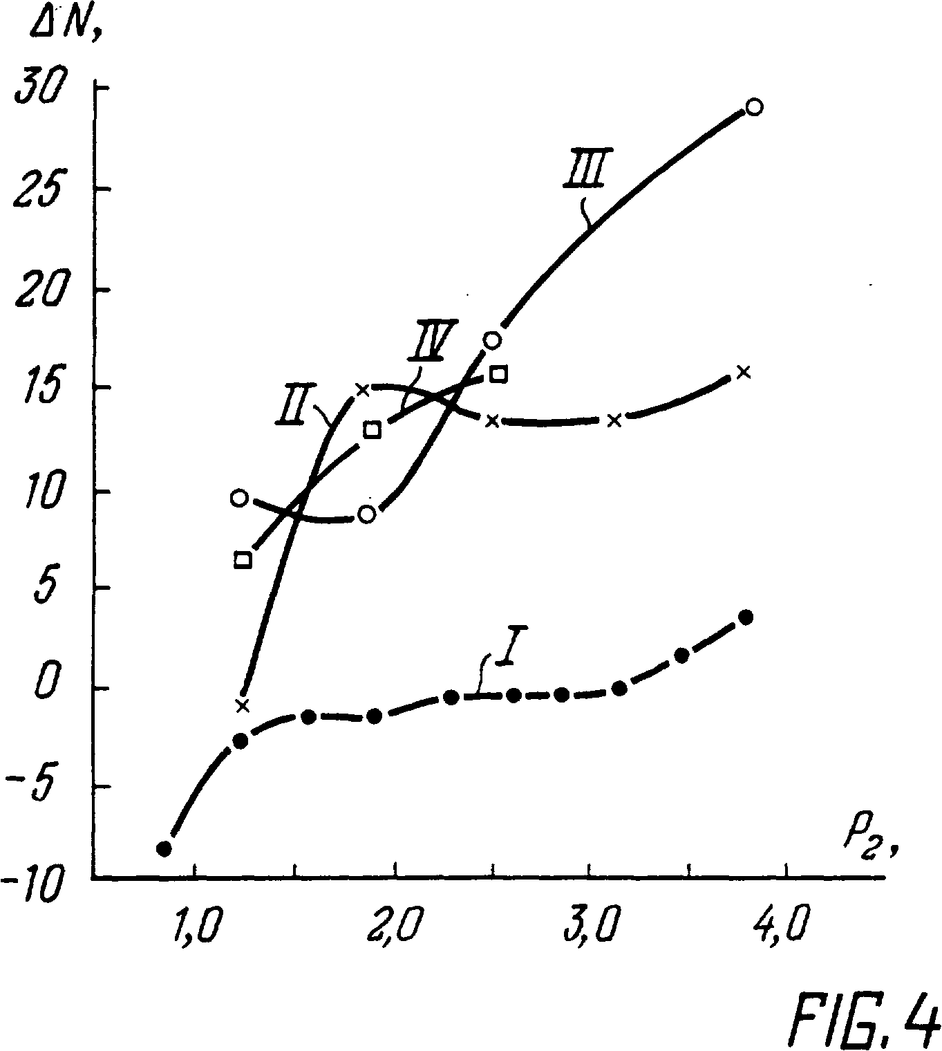
The graph in Fig. 4, shows the dependencies of the power difference (ΔN) of heat release and power consumption on the ratio of constant and alternating pressure in the activator. Said dependence was determined by the present method, using tap water at a temperature of 20°C as the treated substance.
The variable pressure is plotted on the x-axis, and the power difference (ΔN) is plotted on the y-axis. Curve I on the graph corresponds to the static pressure P1 = 0, curve II to the static pressure P1 = 0.6 MPa, curve III to the static pressure P1 = 0.8 MPa, curve IV to the static pressure P1 = 1 MPa.
From these graphs, the boundary of the declared interval of the ratios of variable and static pressures is clearly visible. Everything that lies to the left of 2.3 MPa (graph I), i.e. the variable pressure P2 is less than 2.3 MPa at a static pressure P1 = 0, does not satisfy the proposed pressure ratio P1 and P2, and the amount of energy released is less than the amount of energy consumed. With an increase in the variable pressure P2 to more than 2.3 MPa, i.e. subject to the specified ratio of P1 and P2 , the released energy is greater than the energy consumed.
For graph II, where the static pressure P1 is 0.6 MPa, everything to the left of 1.2 MPa does not satisfy the proposed ratio, and the amount of energy released is less than the amount consumed.
Similarly, by extrapolation, it is possible to determine the area in which the energy consumed is less than that released for schedules III and IV.
Fig. 5 shows a graphical dependence of the difference in power (ΔN) heat and power consumption from the ratio of P1 and P2 when implementing the proposed method in a device of lower power.
graph V - corresponds to the static pressure P1 = 0.1 MPa,
graph VI - P1 = 0.2 MPa,
graph VII - P1 = 0.3 MPa,
graph VIII - P1 = 0.4 MPa,
graph IX - P1 = 0.5 MPa.
From these graphs V, VI, VII, VIII, IX, as well as from graphs I, II, III, IV, shown in Fig. 4, it can be seen that only when the specified ratio of P1 and P2 is fulfilled, the released energy is greater than the energy consumed. Moreover, for graph V it is seen that to the right of the value of P2 = 26 MPa, i.e. if the above ratio is not observed, the released energy becomes less than that consumed.
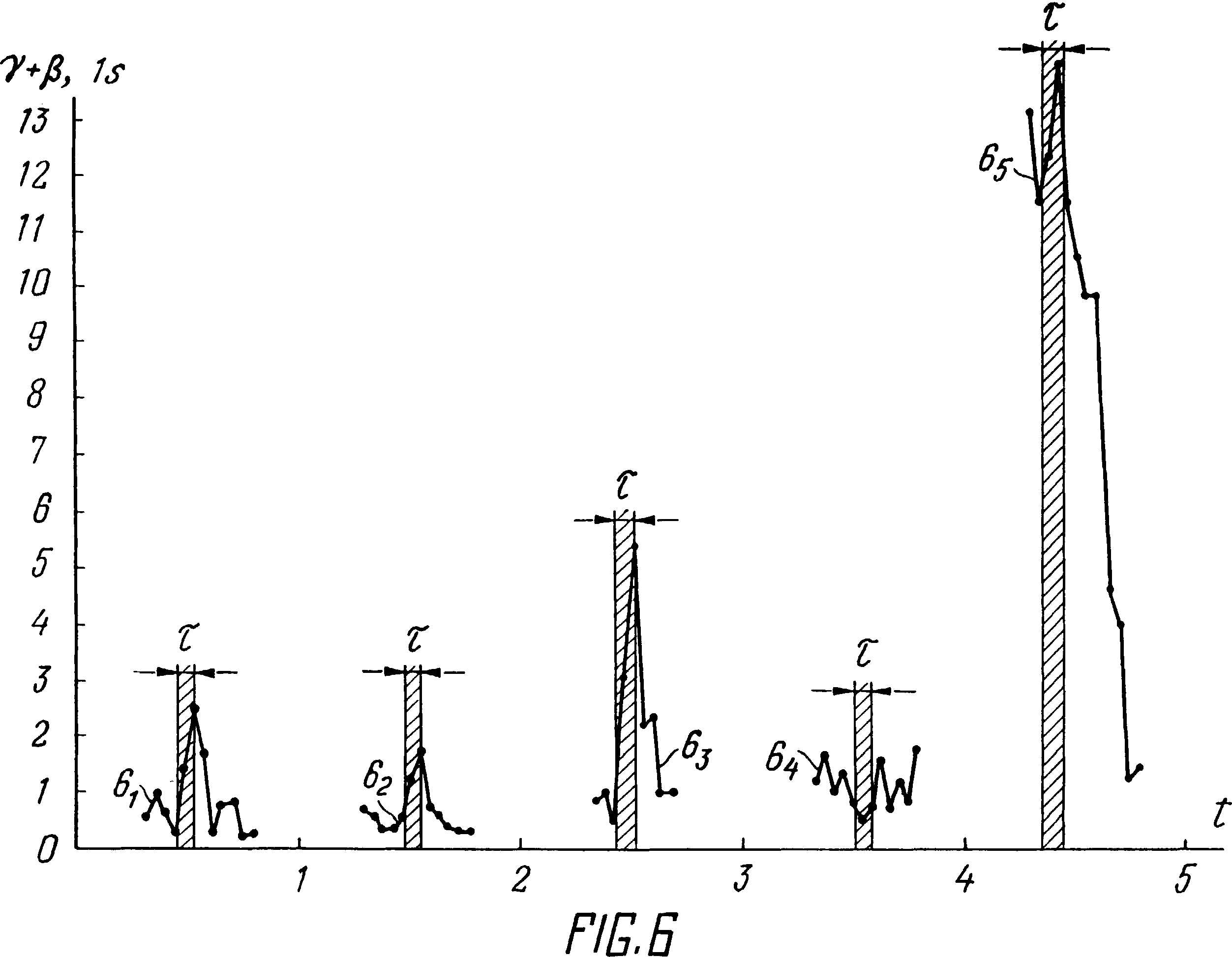
Since the proposed method of obtaining energy is characterised by the practical absence of ionising radiation, to confirm the occurrence of nuclear reactions in cavitation bubbles, we processed liquids in Figs. 6 and 7. Graphical dependencies of γ + β-radiations are presented for the treatment of tap water at a temperature of 20°C with various additions of stable isotopes of various substances. The y-axis gives the average value of the number of γ-quanta and β-particles in one second, recorded by the detector 13 of the radiometer 12 (Fig. 2). Averaging is given for each hour of measurement. The x-axis shows time (t) in hours and days. In addition, the x-axis in Fig. 6 and 7 marked the time (τ) of the ultrasonic activator. Thus schedule 61 shows the relationship of γ + β- radiations with tap water treated at 20°C with the addition of air, in an amount of 1.8 × 10⁻⁶ kg/s, in accordance with the proposed method. The schedule 62 the same with the addition of air in the amount of 3.6 · 10-6 kg/s, schedule 63 the same with the addition of air in the amount of 0.9 · 10-6 kg/s, schedule 64 the same with the addition of carbon dioxide 2 · 10-6 kg/s, schedule 65 is the same with the addition of carbon dioxide in an amount of 10-6 kg/s.
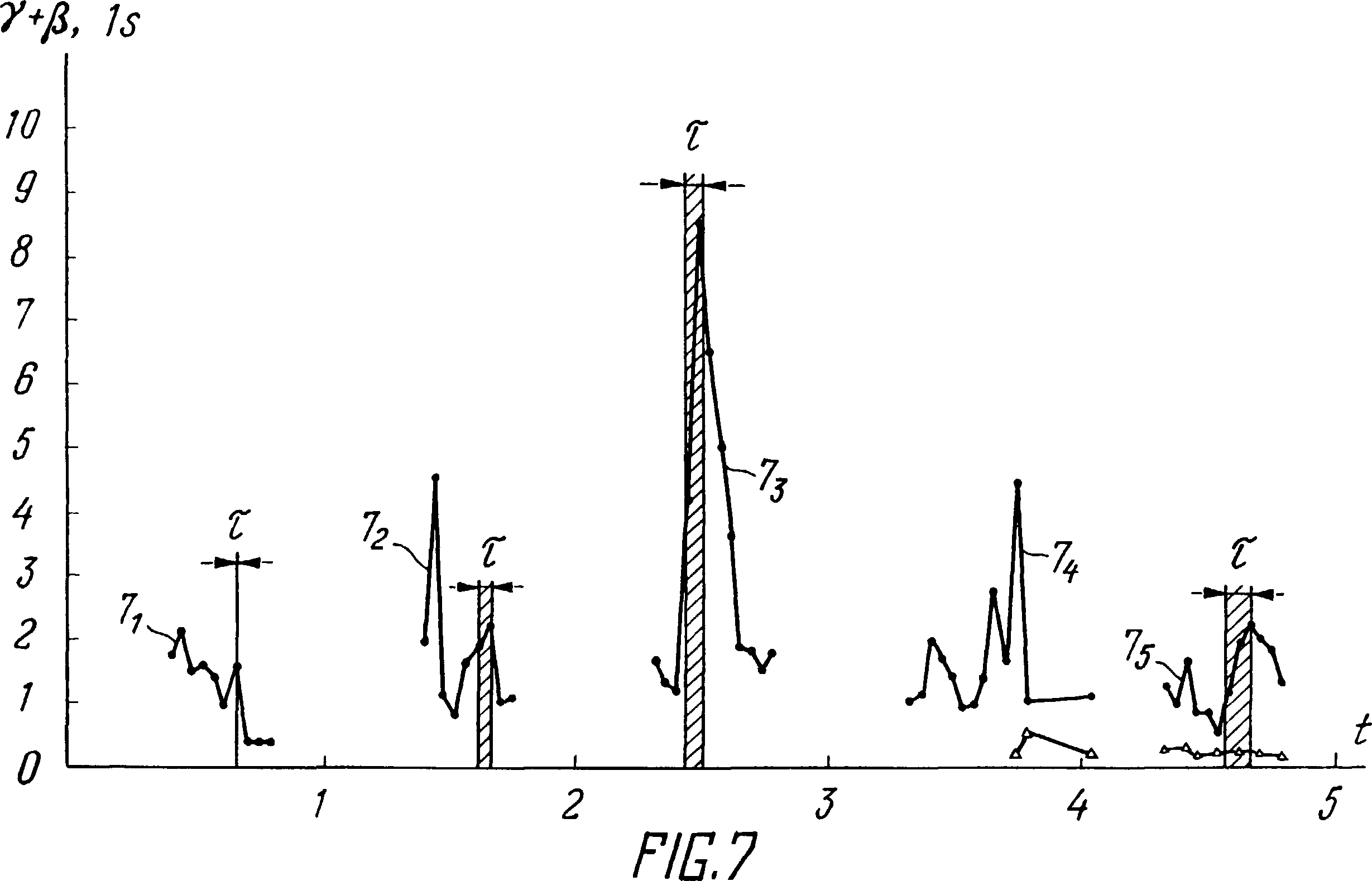
Graph 71 (Fig. 7) reflects the dependence of γ + β- radiation detected by the detector 13 on the residence time of the latter in the core. Graph 72 of Fig. 7 shows the dependence of γ + β- radiations with tap water treated at 20°C with the addition of carbon dioxide in an amount of 4 × 10⁻⁶ kg/s, graph 73 same with the addition of carbon dioxide in an amount of 2 · 10-6 kg/s, graph 74 reflects the dependences of γ + β radiation without activating the ultrasonic activator, recorded on the surface of the activator (indicated by dots) and at a distance of 13 m from the activator (indicated by Δ), graph 75 is the same as graph 72 with the addition of carbon dioxide in the amount of 16 x 10-6 kg/s and the dependence of γ + β-radiation, recorded at a distance of 13 m from the activator (indicated by Δ).
The graphs shown in Fig. 6 show that when the ultrasonic activator is switched on, i.e. when water is treated at 20°C and the ratio of alternating and constant pressures is within the specified limits, there is an increase in γ + β-radiation, which is only possible during nuclear reactions.
Similar studies were carried out when sodium carbonate (Na2CO3 ), gasoline, lithium chloride (LiCl) and other substances were added to tap water. The results of the recorded γ + β- radiation are similar to those presented in Fig. 6 and 7.
The increase in neutron radiation, which confirms the occurrence of nuclear reactions in the implementation of the proposed method, is illustrated in Fig. 8 and 9.
Fig. 8 depicts a graph of neutron radiation of the natural background for several hours. The neutron flux (n, 1/sec) is marked on the y-axis, time (t) in hours on the x-axis.
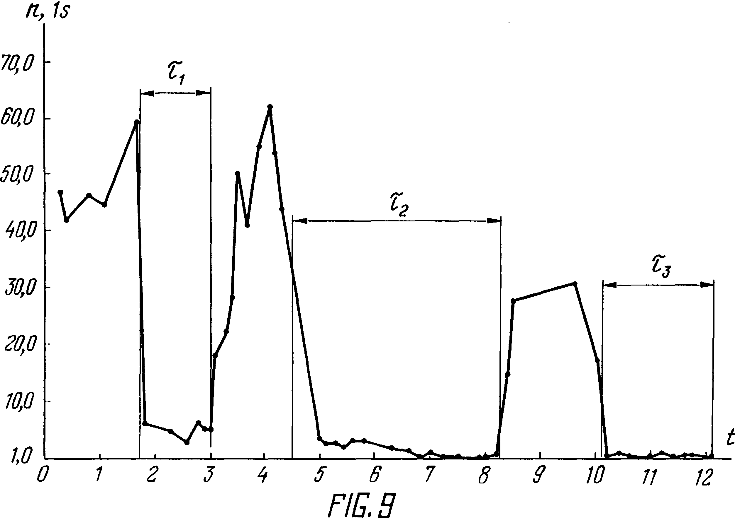
Fig. 9 is a graph of neutron radiation during operation of an ultrasonic activator, i.e. when implementing the proposed method and observing the ratio of variable and static pressures, when processing tap water with a temperature of 20°C, with the addition of lithium chloride (LiCl). Figure 9 also shows three periods, indicated by the time τ1 , τ2 and τ3 during which the detector 15, of the neutron radiometer 14, was installed at a distance of respectively; 0.5, 1.25 and 3.2 m from the surface of the ultrasonic activator.
When comparing the graph depicted in Fig. 8 with the graph depicted in Fig. 9, it is seen that the neutron radiation during operation of the activator is significantly higher (by several orders of magnitude) than the natural background. This once again indicates that when implementing the proposed method in the cavitation bubbles of the treated fluid, nuclear reactions occur.
Similar studies on neutron radiation were also carried out when other components (for example, gasoline) were added to the liquid to be processed, which made it possible to increase neutron radiation to a level that can be measured with existing instruments. These studies have led to similar results.
Thus, the use of the proposed method allows on an industrial scale to obtain the energy generated as a result of the strong interaction of elementary particles of the processed substance.
The easiest way is to use the proposed method on an industrial scale is in the field of heating and hot water supply for civil and industrial facilities. For this, it is necessary to connect the device, for implementing the proposed method, to the heating and hot water supply system of the facility, for example, in heating, distribution and pumping stations.
Using the proposed method is economically advantageous because, firstly, in this case, the capital costs are reduced to almost zero. There is no need to build boiler rooms, fuel depots, access roads, transport pipelines and much more. Secondly, the amount of energy produced is several times higher than the energy consumed. Thirdly, the environment is not polluted by fuel losses during extraction, transportation and its combustion products.
Claims (1)
A METHOD FOR ENERGY PRODUCTION, including feeding a substance in a liquid phase to a treatment zone and creating cavitation bubbles in a substance, characterised in that cavitation bubbles in a substance are created by creating a periodically changing pressure having constant and variable components, and these components are selected from the following ratios:
P1 = from 0.3 to 0.7 (P2 + P3); and
P2 + P3 - P1 = from 1 to 10 σ,
in which:
P1 - represents the constant pressure component (in MPa),
P2 - represents the variable pressure component (in MPa),
P3 - represents the saturated vapour pressure (in MPa) of the substance being treated at the temperature at which it is fed into the treatment zone, and
σ - is the tensile strength of the substance being treated at the temperature at which it is fed into the treatment zone (in MPa).
Thankyou for listening to RemoteView.ICU


