
ULTR - Reverse engineering the Kladov cavitator
ULTR - Reverse engineering the Kladov cavitator
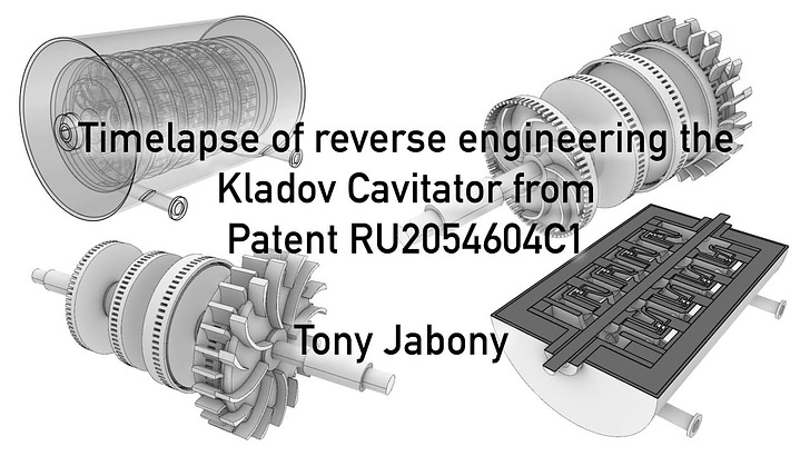
Tony Jabony

Tony Jabony shares a video of him using his masterful 3D skills to do a first pass reverse engineering of the Kladov Cavitator with reference to the available detail in the patent number RU2054604C1. Files in various formats are available below as are comments on the modelling work so far. If you have expertise in the various aspects of pump design, please share your thoughts.
Huge thanks to Tony for this timely contribution.
Timelapse of reverse engineering from patent
3D Files
These are available for people to download and use freely. If you produce a new model or animation using these resources, please share back.
Clipping Animation
Tony’s comments
“The drawings in the patent are pretty detailed, but there are still many variables and discrepancies in the drawings that need to be addressed before it can be turned into a make-able 3D model.
Just like with the Windhexe, the patent drawing is enough to communicate the workings of the apparatus without disclosing too many details like dimensions, materials, etc.
I was happy that the patent disclosed a lot of information on the ratio between the area of the impeller inlet and the total area of the impeller cavitation slots combined. This gave me a couple of parameters that really helped with designing the impellers.
The rest of the impeller/diffuser geometry is still a bit vague in the drawings, also the amount of cavitation holes had to be multiplied from 45 to 72 to get the right ratios and total area correct.
The volute inlets are not the same in the different views, so I had to find a proper geometry somewhere in the middle. There are no fasteners, no mountings no waterproofing seals etc present in the drawings.
The detail I am worried about the most is the current spacing between the impeller and the stator cavitation ring. It's pretty large and it might nullify all of the up and down pressure waves generated by the passing of cavitation ports by being this large.
Another strange thing was that the diffuser vane geometry flips direction and reduces significantly in numbers in the drawings.
The main thing I wanted to do with this version is to reverse engineer the drawings from the patent into a useable 3D model as accurately as possible according to the original drawings. The next step is to figure out if there are any crucial mistakes in this as is and how to revise this design in a make-able 3D model without losing the crucial working elements.
I'm not really familiar with designing and or working with pumps and their geometries so this was a very nice modelling exercise.
All feedback and input is welcome and if the community has any great comments or ideas that would be very useful for converting this design into a make-able prototype, [please post them in the comments below].”
Way forward
If there are industrial partners or engineering companies, say those with CNC facilities that could assist us ‘spin up’ this research thread, please reach out.
I made an attempt to explain what I think is happening internally after looking over the patent description.
Images posted here with descriptions: https://imgur.com/a/opv5SBB
Hopefully it is clear enough to make sense. It was all done on mobile so forgive the crudeness.)
https://youtu.be/RTEWLSTyUic?si=UXk1Urzy2P-Cczn-
55 mins to 56 mins relating to this subject.
T. T Brown.