The Device And Principle Of Operation Of The Device For Focusing Particles Of Dark Matter - Magnetic Monopoles
Belgorod Research Group Shakhparonov I.M.
Pre-amble
Today Dmitry Kolokonov replied to my request for information on making EVOs with Möbius strips.
Dear Bob, thank you for interest to my research. That's very kind of you to propose translate my slides into English. Of course I will send them to you in the near future.
I would also like to draw your attention to the hypothesis explaining the occurrence of a plasmoid in Shakhparonov's discharge circuits. I outlined it in my preprint published on my ResearchGate page. This hypothesis is based on the theoretical assumptions by Professor Rodionov. I think it will be interesting for you to get acquainted with his works as well.
A summary of his theory can be found on the website of our Society, the full texts are published here. By the way, you will find there selected works of Ivan Shakhparonov.
We were friends with him for more than 30 years and during his lifetime I was vice-president of the Belgorod Research Group, which he headed.
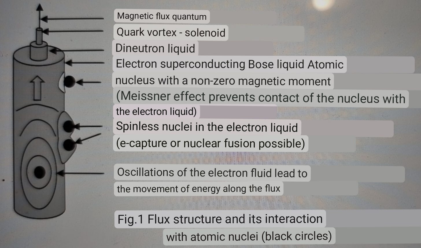
One of the papers above has a diagram (that I have roughly translated below) showing how the matter proposed by Rodinov is composed and how it can interact with ordinary matter.
Below, I have roughly translated a short paper that describes how to build the apparatus to make monopoles.
CAUTION, this may produce dangerous radiation.
The Device And Principle Of Operation Of The Device For Focusing Particles Of Dark Matter - Magnetic Monopoles
Belgorod Research Group Shakhparonov I.M.
Recently, there has been an increased interest in studying the properties of magnetic monopoles. To power undirected circuits that emit magnetic monopoles, of course, resonant generators (Tesla generators) are suitable, but they are dangerous to use, as they develop large voltages. When short-circuited to a nonlinear load, which is an undirected circuit, efficiency, and hence k.p.d., they fall sharply. This article provides data that can help researchers in creating effective circuits of devices that develop large pulsed currents. The article provides an electrical diagram of the basic apparatus for obtaining magnetic monopoles.
In the first works on the study of the properties of magnetic monopoles (MM), we used a resonance transformer (Tesla generator), but later, with an understanding of the physics of the process, we abandoned generators of this type and switched to avalanche circuits on transistors (Figure 1).
The proposed scheme of the generator is very simple, and almost does not require adjustment. The correct assembled circuit works immediately. The only thing that is required is to adjust the frequency of the pulses. To do this, connect the oscilloscope to the output wires that go to the load and using a shunt in the form of a Rogovsky belt, measure the current, achieving its maximum value using the capacitor C2. In areas where current surges are observed in the network, it is necessary to use stabilizers. To do this, a parametric stabilizer is connected parallel to the capacitor C1 from two zener diodes in series. type KS 650A1 and sequentially with them resistor MLT-1-1kOhm.
Particular mention should be made of the winding of the untying transformer Tr and the undirected circuit (NDT). They must be coordinated. The cross-section of the metal coating of the NDT must be less than or equal to the cross-section of the conductor of the transformer Tr. In order for NDT to focus magnetic monopoles, NDT must have dimensions of multiples of 137. For example, the length of the tape must be 137 mm, and the width of the conductive layer 137/2 and the thickness of the dielectric 137/100. We emphasize that the number 137, when determining the dimensions, for example, of a Möbius sheet should always be divided or multiplied by integers.
Special attention should be paid to the winding wire of the transformer Tr. It is difficult or impossible to get the right cross-section wire. But you can make it yourself, because the length of the wire is small. Take a wooden rail, 1 meter long. On it along the winding wire winding section, so that the harness was at least 6 insulated cores. Then, removed from the rail, the ends are tinned, twisted and wound onto a ferrite ring. In this way it is possible to make transformers with wire of very large cross-section without fear of splitting the ferrite ring.
The (Figure 2) shows the oscillogram of current pulses of the above design obtained using Rogowski's belt.
Parts list
It should be added that the circuit can also use more powerful 900 series transistors, e.g. KT 907A, KT 930A or B. When selecting transistors, you should consider that the higher the capacity of the n - p junction of the transistors, the lower the frequency that can be achieved. Note that a significant disadvantage of such circuits is the possible breakdown of the transistors. In this case all transistors fail and must be replaced. Such a phenomenon is possible when the transistors are overloaded, although they are well protected by diodes VD5 and VD7.
Literature
Лавинныетранзисторыитиристоры.В.П.Дьяконов,Москва,СОЛОН-ПРЕСС,2008.
Avalanche transistors and thyristors. V.P. Dyakonov, Moscow, SOLON-PRESS, 2008


Does anyone know what happened to the website and links mentioned by Kolokinov above, http://materialucida.com?
Absolutely fascinating. Thanks Bob.